We include all criteria of ductile detailing which is influence the design parameters of beam. Also included shear reinforcements criteria as per IS 13920
In the case of ductile detailing of structure elements, we provide reinforcement as per earthquake force. Means the earthquake taken under consideration During ductile detailing of beam.
Ductile detailing of Beams
Ductile detailing of beam includes the following criteria.
Size of beam
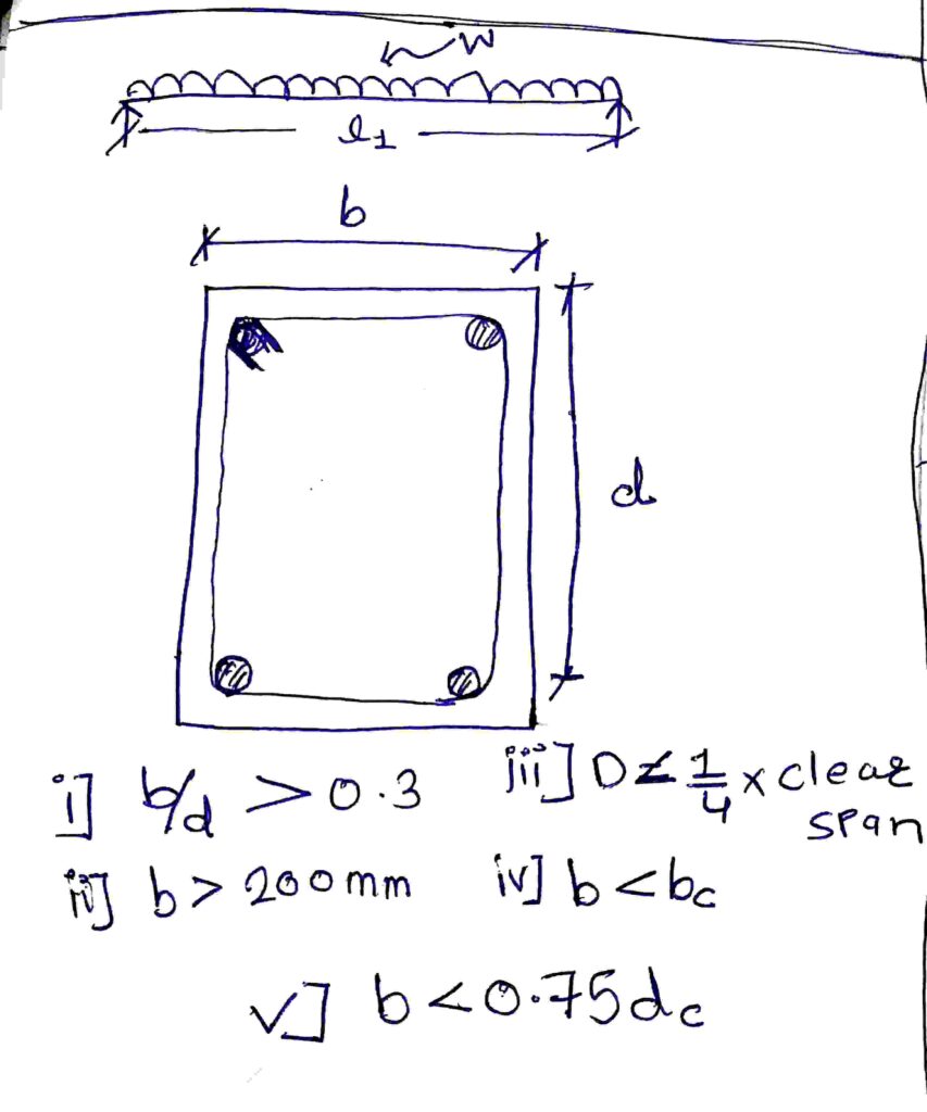
- The width to depth ratio of the beam should be more than 0.3
- The minimum width of beam is 200mm.
- The depth of beam should not be more than 1/4 of clear span. This may not apply to the floor beam of frame staging of elevated RC water tank.
- The width of the beam should not be more than the width of the supporting column.
- Width of beam should not be more than 0.75 breadth of supporting column.
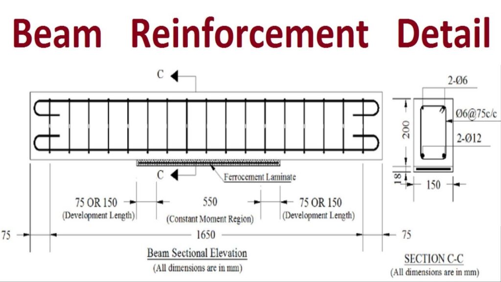
Longitudinal Reinforcement
Beam should have at least two 12mm dia bars on the top and bottom face. Means at least one 12 dia bar located on every corners of beam.
The minimum longitudinal steel ratio on any face at any section of beam is
Pmin = 0.24x √fck/fy
The maximum longitudinal steel ratio provided on any face at any section is 0.025.
Longitudinal steel on bottom face of beam, at near the face of the column, shall be at least half the steel on its top face at the same section.
Longitudinal steel in beam at any section on top or bottom face shall be at least 1/4th of longitudinal steel provided at the top face of the beam at the face of the column. When the top longitudinal steel in the beam at the two supporting column faces is different, the larger of two shall be considered.
At an exterior, top and bottom bars of beams shall be provided with Anchorage length beyond the inner face of the column.
Anchorage length= Development length (Ld) + 10 times dia of bar – 90° bend allowance.
Splicing of Longitudinal Bars
In case of lap splices of longitudinal bars, the following criteria of IS 13920 should be kept in mind.
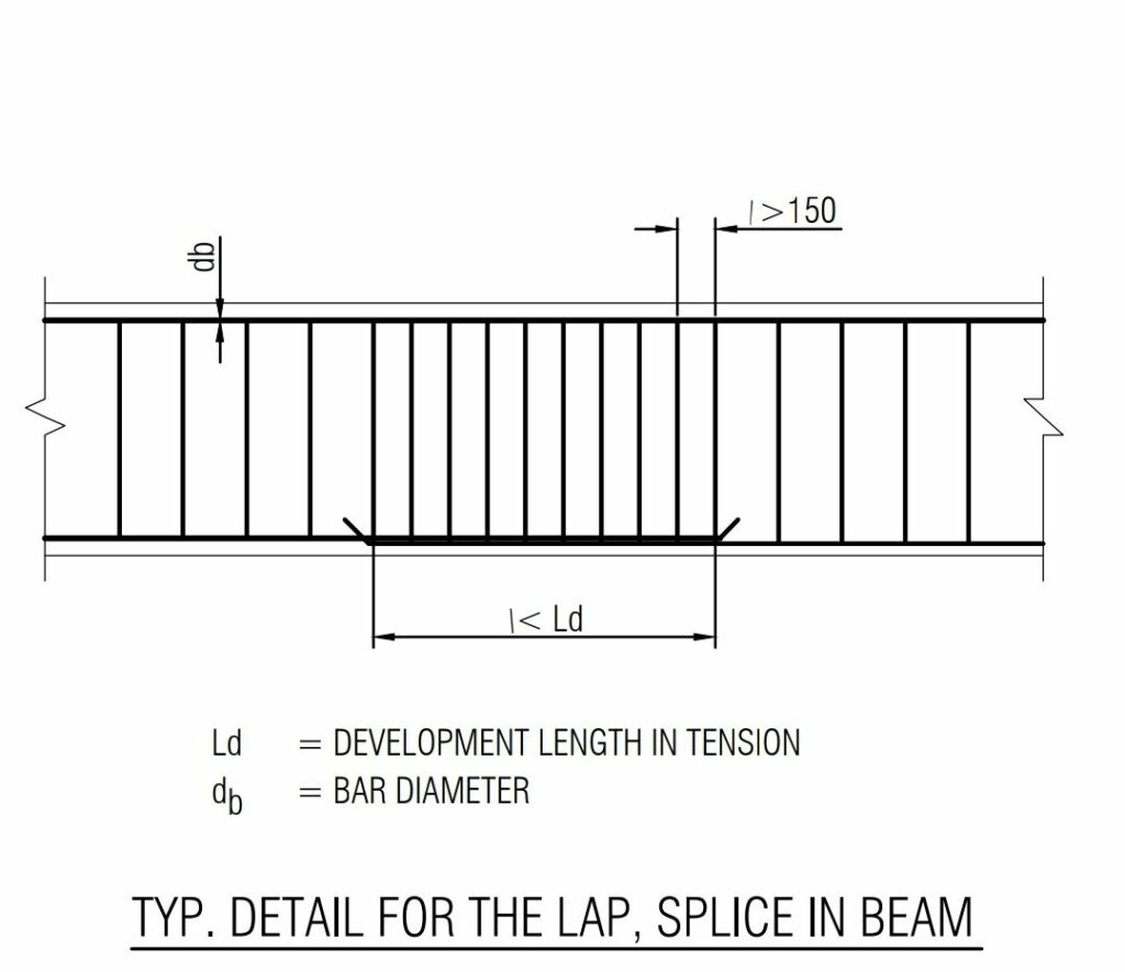
- The spacing of link over the splices shall not exceed 150mm.
- The Lap length should not be less than the development length of the largest longitudinal bars in tension.
- Lap splices should not provided within joint.
- Lap splices should not provided within a distance of 2d from face of the column.
- Lap splices should not provided within quarter length of beam adjoining the location where Flexural yielding may occur under earthquake effects.
- Not more than 50% area of steel bars on either top or bottom face shall be spliced at aany one section.
- Transverse reinforcements spacing over a lap splices provided should be as per closed spacing criteria.
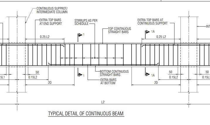
Transverse Reinforcements
As per IS 13920, Only Vertical links or stirrups shall be used in beams. Inclined links shall not be used. And the link hooks should be bent at 135°.
The minimum diameter of a link shall be 8mm.
Close Spacing of links

Spacing of link over a confinement zone ( 2d length) at either end of beam shall not exceed,
- d/4 (effective depth / 4)
- 8 times the diameter of the smallest longitudinal bar (main steel).
- 100mm.
Whichever is less, should be used as a spacing of Stirrups.
Closely spaced links shall be provided over a length of 2d at either end of beam. So over the remaining length of beam, vertical links spacing should not exceed d/2 of beam.
The first stirrup of beam provided within 50mm length from the face of column beam joint.
]]>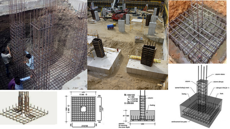
There’re various categories of footings such as combined footing, isolated footing, raft footing, strip footing, pile foundations that could be utilized based on constructional requirement and conditions of the ground.
Reinforcement footing detailing is of great importance for the category of footing and footing constructional blueprint. A fine particularization tells the blueprint condition about the footing considering constructional stability. A fine reinforcement particularization comprises matters such as covering toward reinforcement based on conservation subjects for durability, minimum reinforcement as well as bar diameters, suitable footing measuring, etc.
Isolated Footing Analysis:
Reinforcement covering: The minimum width to main reinforcement in footing must not be less than 50 mm in case footing is alongside surface level straightforwardly, also 40 mm for external open face such as surface leveling PCC. In case surface leveling stays vacant, in that case it is required to lay down a covering of 75 mm to safeguard uneven excavation plane. Considering raft foundation, the minimum covering to reinforcement must be 75 mm in case kept on PCC or right on surface level.
Minimum reinforcement and bar diameter: The minimum diameter for primary reinforcement must not be below 10 mm.
Isolated footing particularization technique: It is recommended that base should be specified in equally blueprint and rise in illustrations.
The isolated footing relates to rectangular or square in outline to abide by constructional requirement and powers functioning on the post. Moreover, spherical or additional forms are utilized for isolated footings as well.
The design of isolated footing is made on the basis of the guidelines set by ACI 318-14.
1. The compressive strength of concrete should satisfy the needs for both strength and stability. As per ACI 318-14, least concrete compressive strength should be 17MPa for normal applications.
2. With adherence to ACI 314-14 section 20.2.1.1, the deformed type steel bars should be used.
3. Factored forces and moments provided at the base of columns are transmitted to the foundation with reinforcement, dowels, anchor bolts, or mechanical connectors.
4. There should be least reinforcement even if the concrete bearing strength is not crossed.
5. Adequate anchorage should be arranged for tension reinforcement if reinforcement stress is not directly relative to the moment like in sloped, stepped or tapered foundation.
6. There should be sufficient anchorage length of both flexural and dowel reinforcement to get rid of bond failure of the dowels in the footing and to resist failure of the lap splices among the dowels and the column bars.
7. As per ACI 318-14 section 13.3, depth of footing over reinforcement should not remain under 150 mm.
8. The depth of the footing should be in such a manner that the shear strength of the concrete remains equivalent or surpasses the critical shear forces (one-way shear and punching shear) developed with factored loads.
9. In sloped, stepped, or tapered foundation, location and depth steps and angle of slope should satisfy design requirements at each section.
10. Concrete cover of 75 mm is necessary when the concrete is cast against soil.
11. With adherence to ACI Code specifications, base area of footing is set from un-factored forces and moments transferred by footing to soil and the permissible soil pressure evaluated through principles of soil mechanics. To get the necessary base area of the footing, the column service loads are divided with permissible net soil pressure of the soil. The net factored soil pressure is equivalent to factored load column loads by the selected footing area.
]]>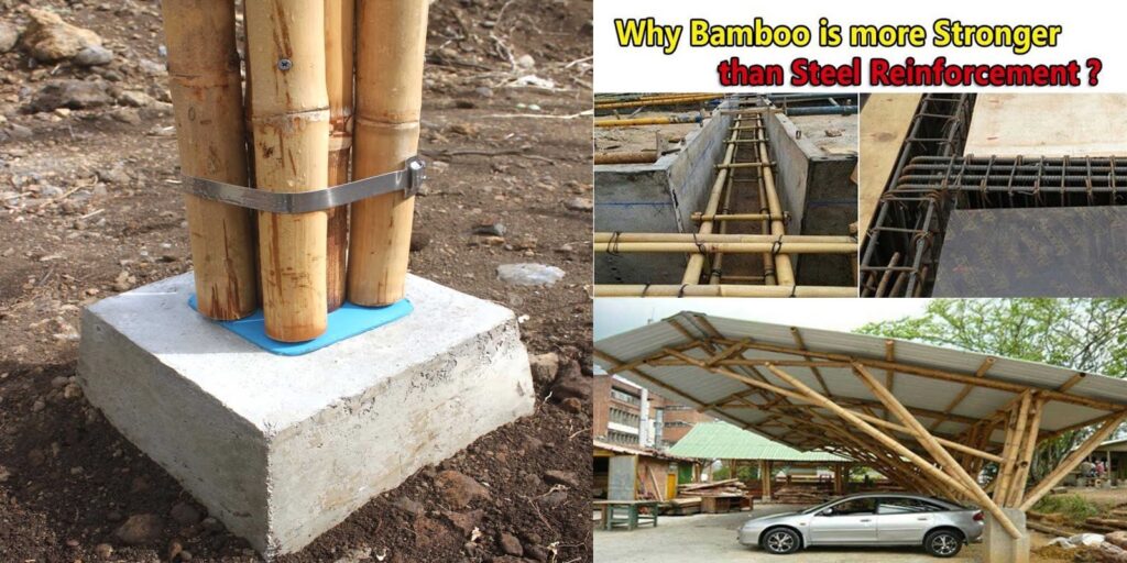
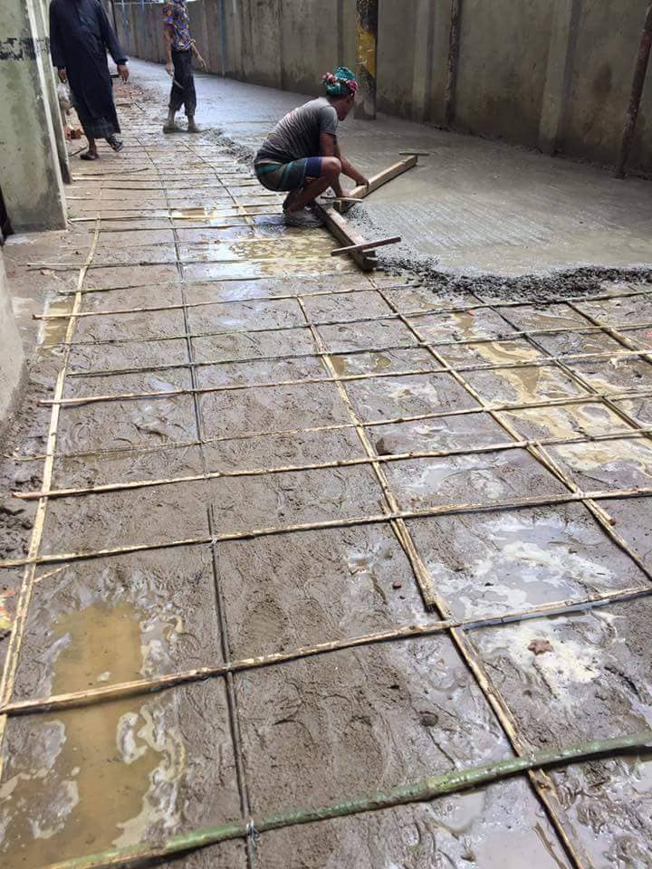
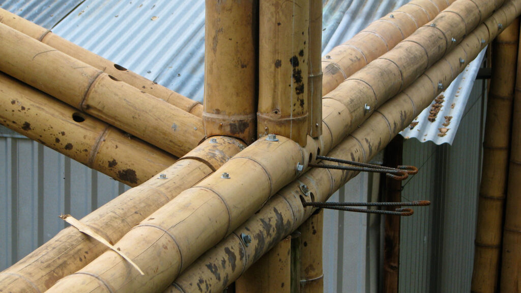
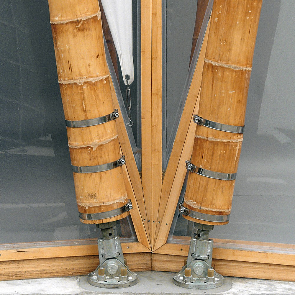
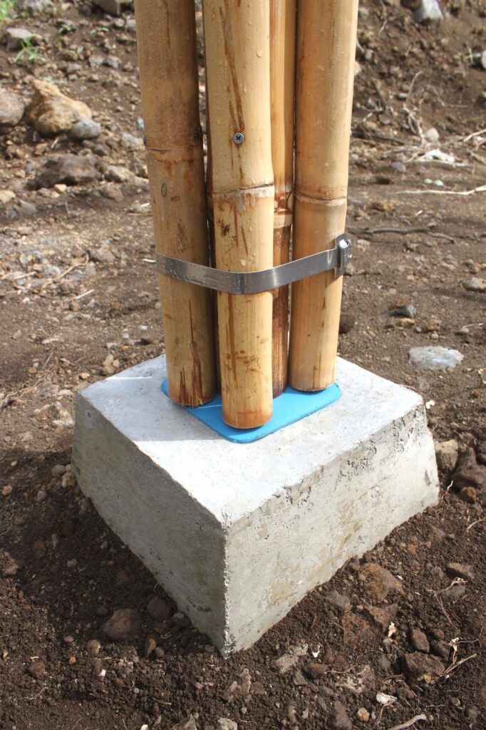
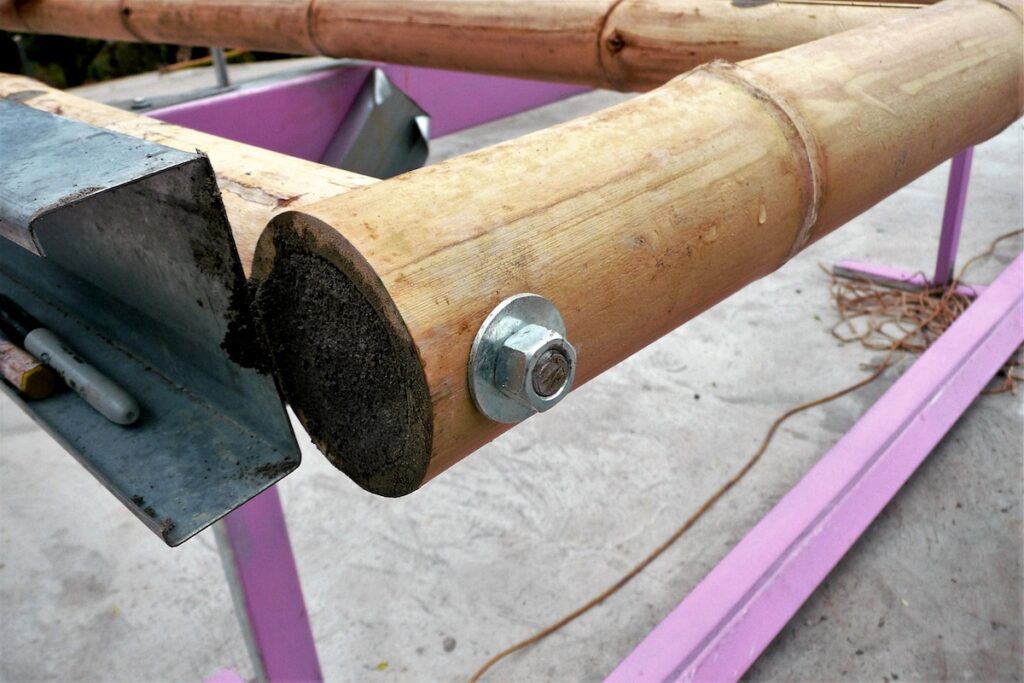
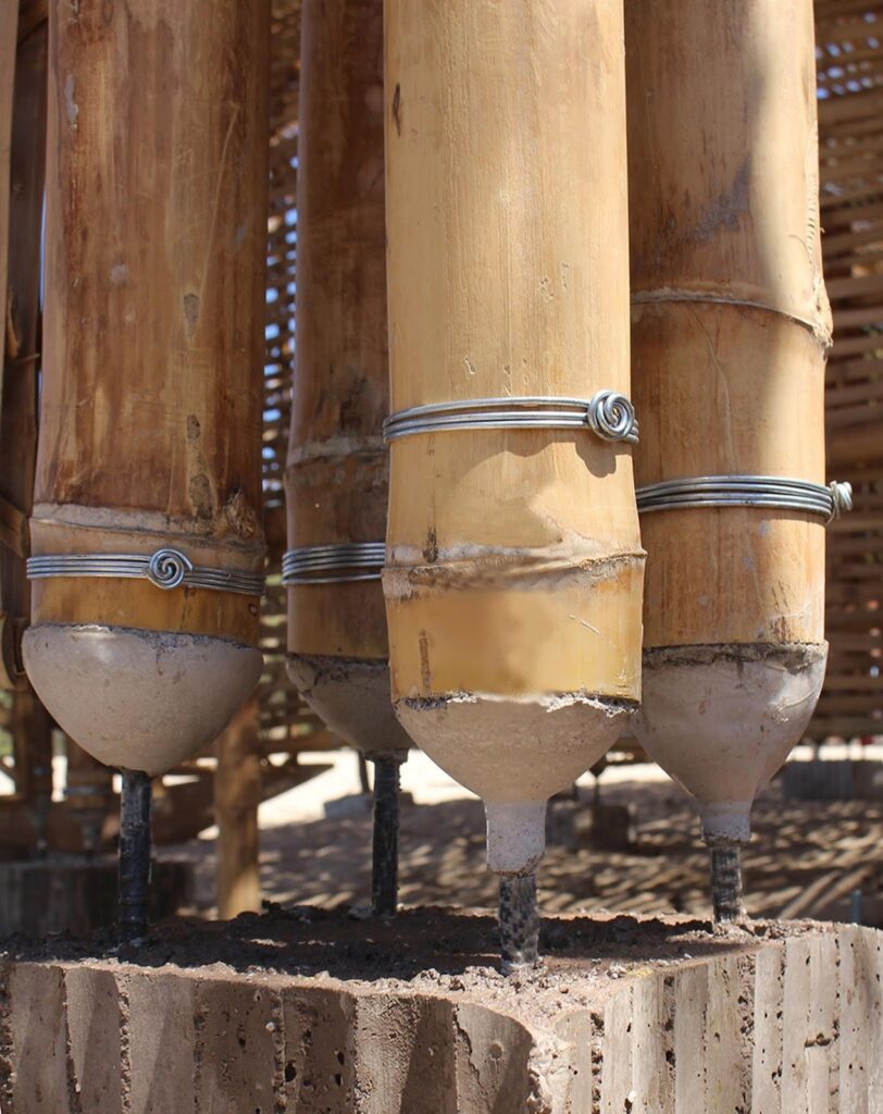
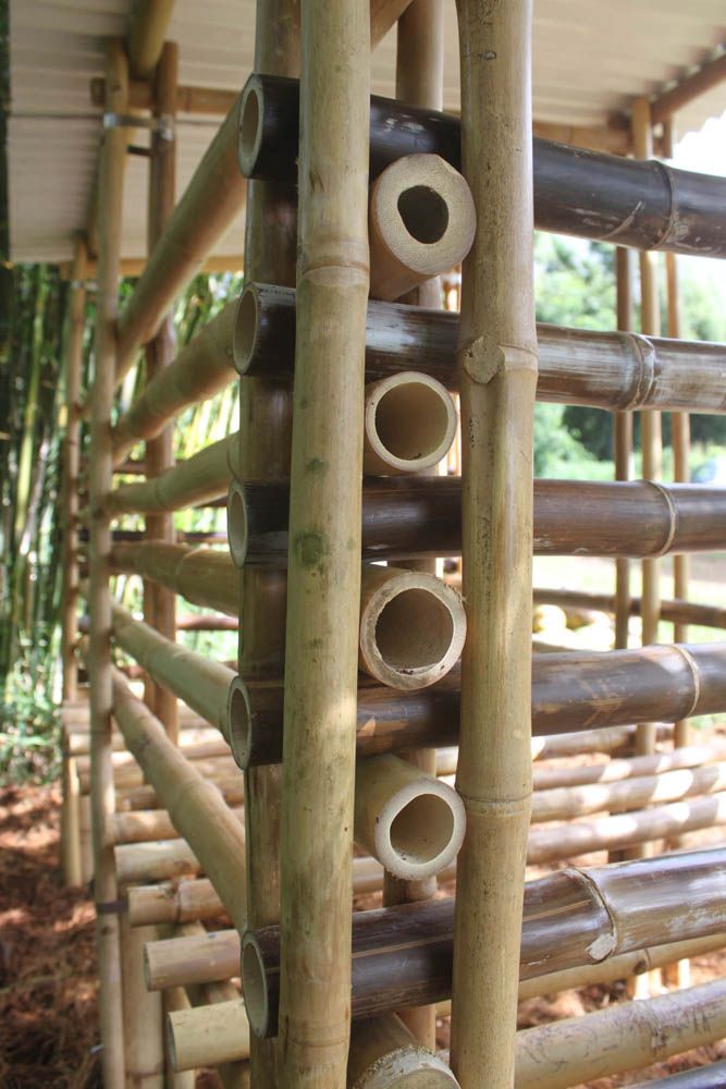
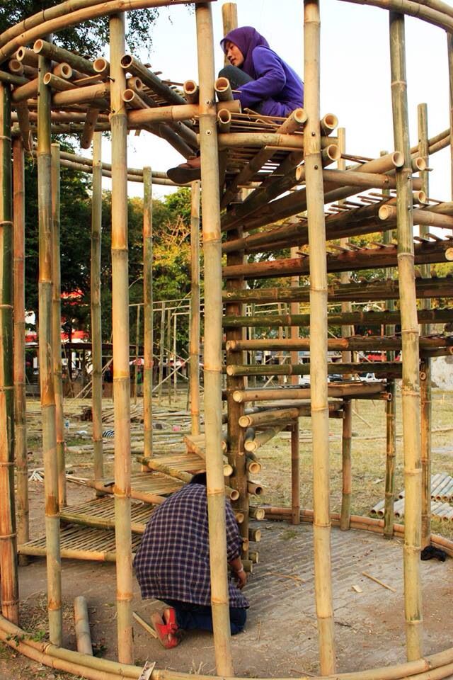
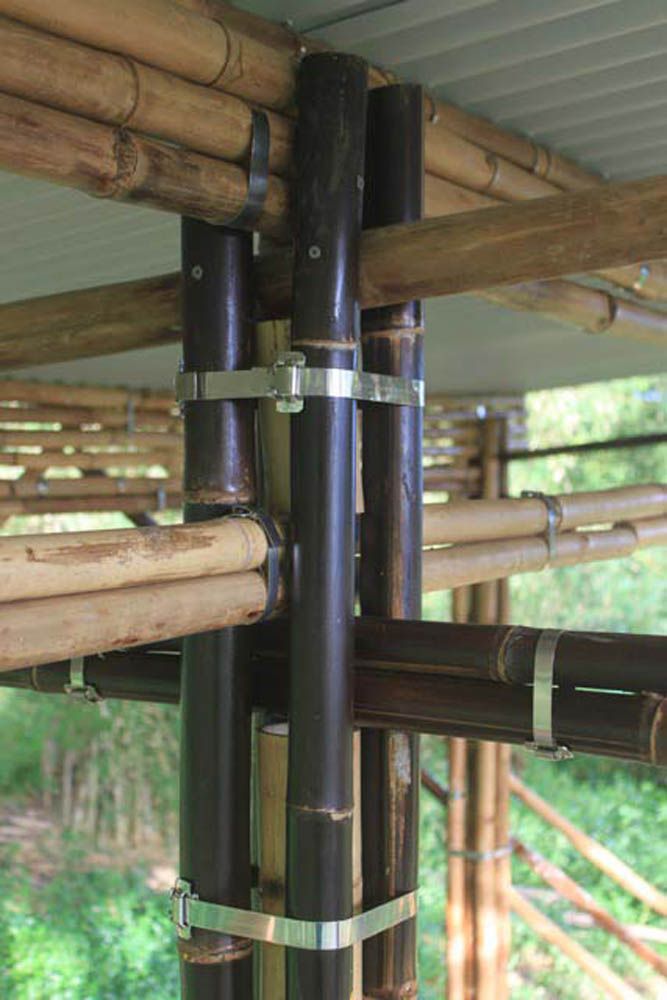
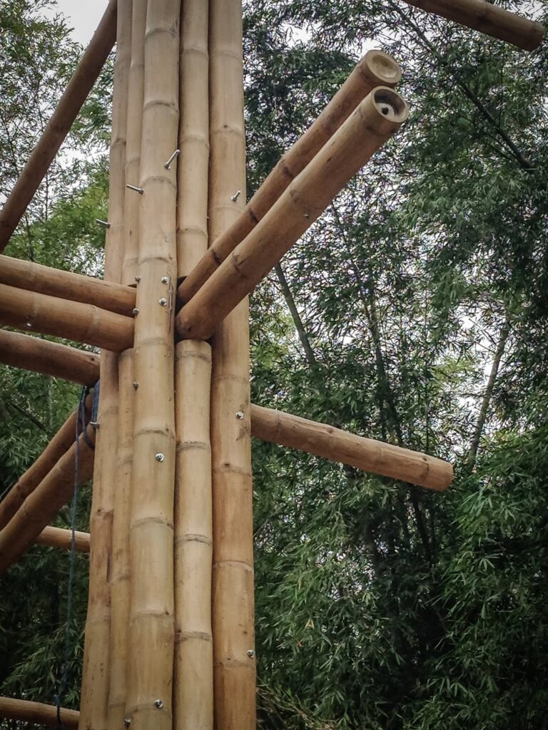
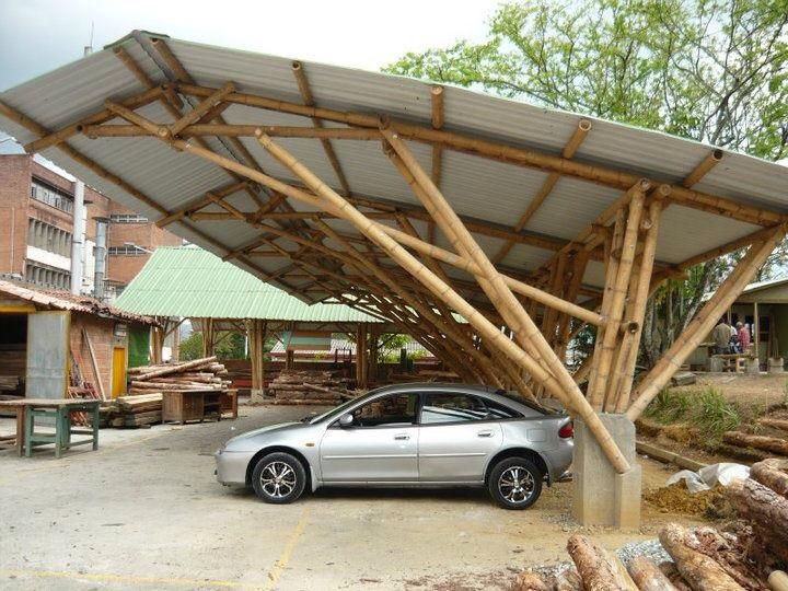
Bamboo has quite a high tensile strength. It is comparable with steel. Apart from this, bamboo has an impermeable protective layer on the outer side, which protects it from rotting due to water, which is a major problem for almost all organic material.
Now in civil engineering, many people are using bamboo in place of steel for reinforcement, but bamboo is an excellent choice for reinforcement in concrete because of its higher strength as compared to steel by weight, the tensile strength Bamboo’s tensile strength is roughly 28,000 per square inch versus steel’s 23,000. Bamboo is stronger more than 6 times of steel reinforcement, On comparison, the energy needed to produce steel is almost 50 times that of this natural product.
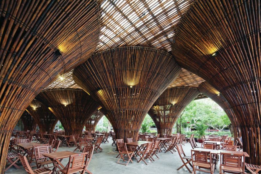
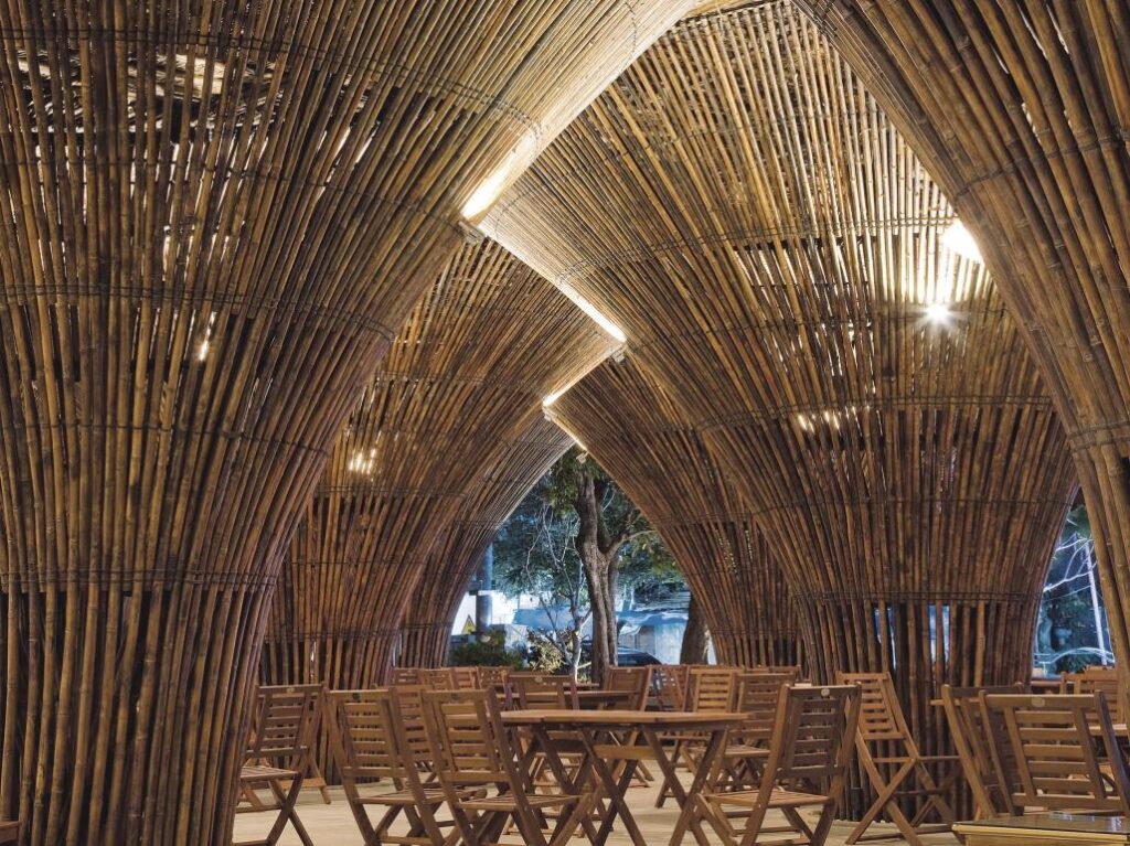
Use of Bamboo and Its Strength In tensile load application, results shown by bamboo are exciting because the ratio of tensile strength to the specific weight of bamboo is six times greater than STEEL.