What Is Bridge Abutment and How Does It Work?
A bridge abutment is a substructure that supports one end of a bridge’s superstructure while also laterally supporting the embankment that acts as the bridge’s approach.
A river bridge’s abutment also protects the embankment from stream scour.
Abutments for bridges can be composed of masonry or reinforced concrete.
Types of Abutments:
The most fundamental types of abutments are as under:
(a) Gravity Abutments:
Its deadweight resists horizontal earth and water pressure. The foundation of such abutments is very broad and substantial. As the name implies, the abutment’s structure is simply put on the ground, and the earth’s gravitational pull keeps the abutment in place.
(b). Gravity Abutments in the Shape of a U:
The wings of this sort of bridge abutment are perpendicular to the face and serve as counter-forts. These abutments are extremely durable. The abutment’s wing walls are at a 90-degree angle (perpendicular) to the bridge’s seat. A U-shaped Abutment consists of a pair of piles spaced equal to the width of the bridges.
Reinforced cement concrete is used to build these types of abutments. Both piles of the abutment are joined to each other at the bottom by a foundation. Both heaps have the same foot.
(c). Cantilever Wall Abutments:
A Cantilever Abutment has two functions: one is to retain soil behind the bridge’s ends, and the other is to support the superstructure of the bridge. Stub abutments are the name given to some types of wall abutments. These abutments are put at the top of fill embankments and are made as short as possible.
Stub abutments often only hold soils that are somewhat higher than the thickness of the superstructure. Stub abutments can be highly cost-effective, but they do tend to lengthen the end spans. Other wall abutments are often built to the full height of the crossing and can be much taller. Although full-height abutments are more difficult to build, they tend to have short end spans.
(d) Full Height Abutments:
A full-height abutment is one that is built at the lower level of the roadway and is designed to sustain the entire embankment. This abutment is costly, and it’s usually used in congested urban and metropolitan areas where structure depth is critical.
(e) Stub Abutments:
They are short abutments built at the top of an embankment or slope of the embankment, usually supported by piles. They are quite difficult to see from above ground level.
(f). Semi-stub Abutments:
A semi-stub abutment is in the middle of the full-height and stub-abutment heights. Unlike stub abutments, which are built at or near the top of the embankment, and full-height abutments, which are built at the bottom of the embankment, Semi-stub abutments are built halfway between the top and bottom of the embankment.
Semi-Stub Abutments are taller than stub-abutments but shorter than full-height abutments because they are taller than stub-abutments but shorter than full-height abutments.
Bridge Abutment’s Functions:
- To transfer loads from a superstructure to the components of its foundation.
- Self-weight, lateral loads (such as earth pressure), and wind loads must be resisted or transmitted.
- To support one of the approach slab’s edges.
- To keep the vertical and horizontal force aspects of an arch bridge in equilibrium.
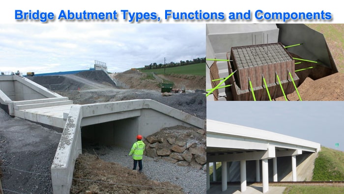
Components of a Bridge Abutment:
Abutments are made up of numerous structural components. Abutments at either end of a bridge typically have the following five components:
- Bridge Seat
- Wing Wall
- Back Wall
- Pile Of The Abutment
- Footing Of The Abutment

- There are seven central bridge designs which have been adapted and enhanced over the years
- While the truss bridge design is seen as the strongest, the suspension bridge design is the one which can stretch furthest
- The crux of any bridge design is a degree of flexibility even though this may look dangerous in strong winds
- The most expensive type of modern bridge is the suspension bridge often costing in excess of $1 billion
- What are the 7 main types of bridges?
- What are the 5 main types of bridges?
- Which type of bridge is strongest?
- What is the most expensive type of bridge to build?
- What is the best type of bridge?
- What is the most common type of the bridge?
There are 7 main Types of Bridges: Arch Bridge, Beam Bridge, Cable-stayed Bridge, Cantilever Bridge, Suspension Bridge, Truss Bridge, Tied Arch Bridge. The way in which the vertical/horizontal stresses are managed dictates the structure of different bridges. In some cases the deck area will be the load-bearing element while in others it will be the towers. There are also designs that transmit tension through bridge cables which allow a degree of flexibility for different terrains.
One interesting factor when looking at different bridge designs is their longevity and the fact they have been around for centuries. Many of the world’s greatest engineers have failed to add any significant improvements to the basic load-bearing designs of years gone by. We will now take a look at the different types of bridges and how they work.
Types of bridges
The 7 main types of bridges are:
- Arch Bridge
- Beam Bridge
- Cable-stayed Bridge
- Cantilever Bridge
- Suspension Bridge
- Truss Bridge
- Tied Arch Bridge
The 5 main types of bridges are:
- Arch Bridge
- Beam Bridge
- Cable-stayed Bridge
- Suspension Bridge
- Truss Bridge
A beam bridge is one of the simplest types of bridge. A perfect example being a basic log bridge – something you may see while out on a country walk.
The deck area traditionally consists of wood plank or stone slabs (often referred to as a clapper bridge). These are supported either side by two beams running between abutments/piers.
Very often you will find other beams, positioned in between the main beams, offering additional support and stability.
The area over which people or vehicles travel will be a simple decking positioned vertically across the underlying beams. This is often referred to as a “simply supported” structure. There is no transfer of stress which you see in arch structures and other types of bridges.
Truss bridges

The truss bridge has been around for literally centuries and is a load-bearing structure which incorporates a truss in a highly efficient yet very simple design. You will notice an array of different variations of the simple truss bridge but they all incorporate triangular sections. The role of these triangular elements is important because they effectively absorb tension and compression to create a stressed structure able to accommodate dynamic loads. This mixture of tension and compression ensures the structure of the bridge is maintained and the decking area remains in-compromised even in relatively strong winds.

Cantilever bridges
When the first cantilever bridge was designed it was seen as a major engineering breakthrough. The bridge works by using cantilevers which may be simple beams or trusses. They are made from pre-stressed concrete or structural steel when used to accommodate traffic. When you consider that the horizontal beams making up the cantilever arm are only supported from one side it does begin to sound a little dangerous. However, the two cantilever arms are connected by what is known as the “suspended span” which is effectively a centerpiece which has no direct support underneath. The bridge load is supported through diagonal bracing with horizontal beams as opposed to typical vertical bracing. Extremely safe and very secure, the design of cantilever bridges is one which still lives on today.


Arch Bridges
There are many different types of arch bridge but they all have central elements in common. Each bridge has abutments, which are used to support the curved arch structure under the bridge. The most common type of arch bridge is a viaduct, a long bridge made up of many arches. The lateral pressure created by the arch span is transferred into the supporting abutments. It is therefore essential that these parts of the bridge remain solid, intact and well founded. You will see many arch bridges with decorative brickwork which is an integral part of the design. Simple yet so very effective an arch bridge can carry everything from pedestrians to heavy rail.

Tied Arch Bridges
The tied arch bridge is a fascinating design which incorporates an arch structure (usually metal) supported by vertical ties between the arch and the deck. The tips of the arch structure are connected by a bottom chord. This acts in a similar fashion to the string of a bow. The downward pressure from the arch structure to the deck of the bridge is translated into tension by the vertical ties. Many people assume that the abutments ensure that the tied arch bridge and arch structure stay in place. However it is the decking/strengthened chord which connects the tips of each end of the arch together. The best example of this is a bowstring which absorbs pressure, keeping both sides of the bow in contact, until it eventually flattens out.
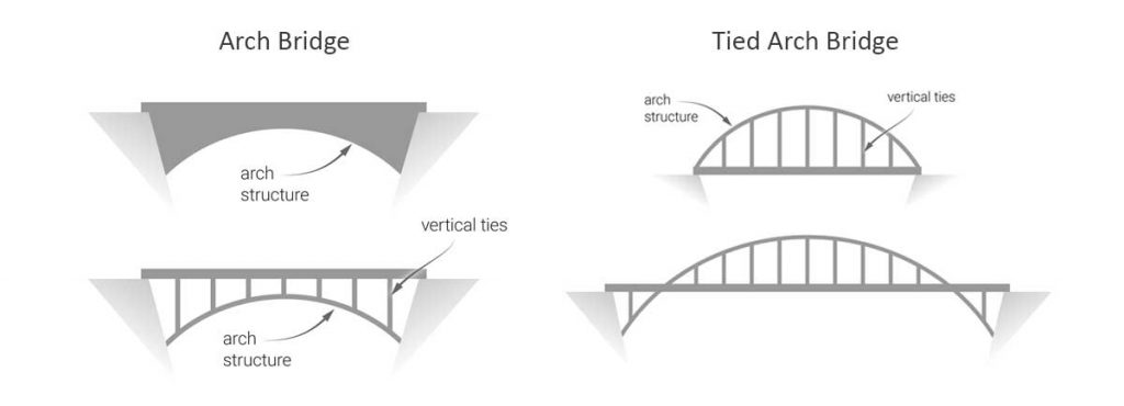
Arch bridge and tied arch bridge comparison.
Suspension Bridges
The structure of a stereotypical suspension bridge looks very simple but the design is extremely effective. The deck of the suspension bridge is the load-bearing element of the structure. This is held in place by vertical suspenders which support the cables. The suspension cables extend out beyond each side of the bridge and are anchored firmly into the ground. It will depend upon the size of the bridge but a number of towers will be installed to hold up the suspension cables. Any load applied to the bridge is transformed into tension across the suspension cables which are the integral part of the structure. As there is some “give” in the suspension cables this can translate into slight, but measured, bridge movement in difficult weather conditions.
